
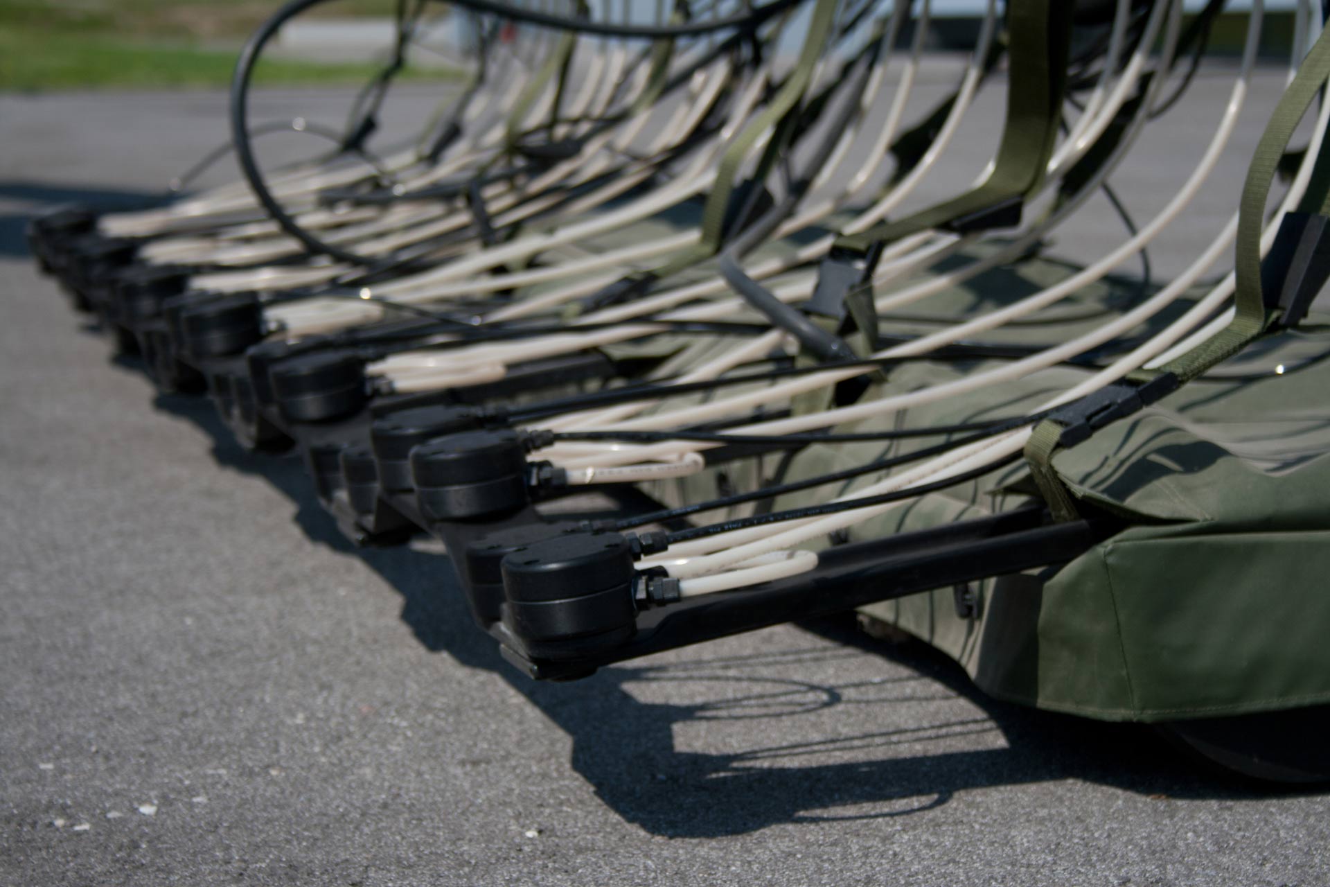
MULTIPLE MARKER NOZZLES
The VAMIDS™ at its 4-m maximum array uses 32 marker nozzles and 2 lane marker nozzles.
MULTIPLE MARKER NOZZLES
The VAMIDS™ at its 4-m maximum array uses 32 marker nozzles and 2 lane marker nozzles.
PERFORMANCE
The VAMIDS™ has a detection width of 4000 mm (157.5″) and weighs 120 kg (264.5 lbs).
PERFORMANCE
The VAMIDS™ has a detection width of 4000 mm (157.5″) and weighs 120 kg (264.5 lbs).
FLEXIBLE ARRAY
The 4-m (157.5″) array can bend from side to side at a +/-56° angle.
FLEXIBLE ARRAY
The 4-m (157.5″) array can bend from side to side at a +/-56° angle.
HEAD DIMENSIONS
Maximum width 4170 mm (164.2″) Length 610 mm (24.0″) Height 150 mm (5.9″)
HEAD DIMENSIONS
Maximum width 4170 mm (164.2″) Length 610 mm (24.0″) Height 150 mm (5.9″)
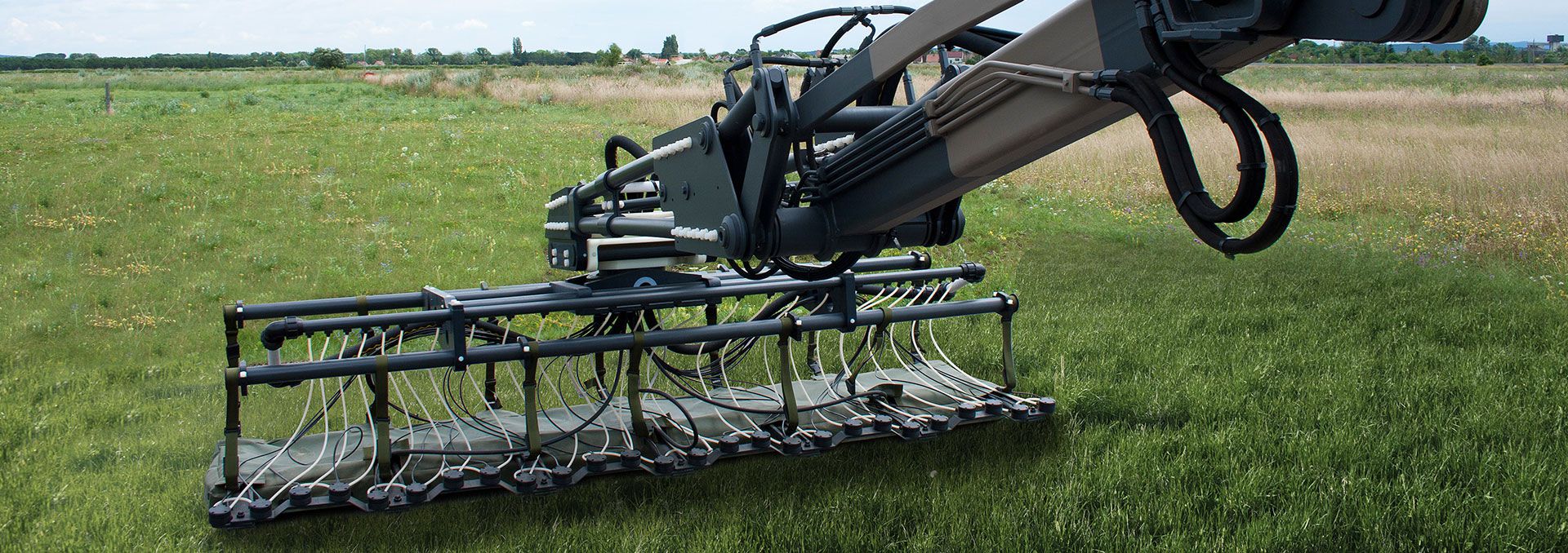
Components
VAMIDS™ is a modular system, which consists of segmented arrays, a control unit, a system console and a marker system.
The segmented flexible array can be arrayed in 1-m steps to a maximum of 4 meters.
The control unit is housed in a watertight, hardy case, with an anti-vibration-mounted military 19” rack. It is ideal for vehicular operations and can withstand harsh environmental conditions.
A system console is the operator interface, enabling the user to quickly and easily set up and operate the system.
The marker system has 8 spray nozzles per meter, plus 2 lane marker nozzles at the outer edges, and accurately marks the location of targets and the scanned lanes.
Depending on the power sources available on the carrier vehicle, such as compressed air, electrical supply, hydraulic supply, and / or auxiliary drive, additional equipment, such as paint pump, paint and water tanks, electric power generator and air compressor is needed to operate the VAMIDS™ marker system.
VAMIDS™ can be mounted on a variety of off-road vehicles, preferably on a medium to heavy MPV (Mine-Protected Vehicle). The VAMIDS™ draw bed is mounted on a rugged outrigger construction, which assures ground contact of the array in uneven terrain. The typical layout incorporates front arm(s) which can be moved both horizontally and vertically and allow the draw bed to be turned around a vertical axis as needed. Another option is a rear arm, drawing a draw mat behind.
VAMIDS™ Manager software
With the VAMIDS™ Manager software, the operator controls all functions and sets all parameters via a user-friendly, Windows-based, graphical user interface.
Main Features
- Highly durable and easy to maintain
- Simple user interface
- Based on Schiebel’s proven mine detection technology
- Real-time monitoring and data recording
- Automatic marking with adjustable marking levels according to terrain conditions
- Continuous lane markers
- Detection head fully maneuverable by an operator joystick

Applications
VAMIDS™ can assist in the clearance of UXO (UneXploded Ordnance) and other ERW (Explosive Remnants of War) and it can help in providing safe conditions in which roads, railways, pipelines, etc. can be (re)constructed.
VAMIDS™ can be deployed in areas of desert, steppe and grassland. A ‘tailor-made’ design for vehicles is already in place, providing an efficient, cost-effective detection system.
VAMIDS™ will mark all detected metal – either to warn following troops or for subsequent investigation with hand-held mine detectors and removal.
Technical
Flexible Array
| Width | 1 m (39.4") (basic element) |
| Marker nozzles | 8 nozzles / Lane marker: 2 nozzles |
| Effective width | 1000 mm (39.4”) |
| Dimensions (W x L x H) | 1170 x 610 x 150 mm (46.0 x 24.0 x 5.9”) |
| Weight approx. | 30 kg (70 lbs) |
| Detection heads | 8 coils |
| Max. bend angle | +/- 14° |
| Width | 2 m (78.7") (recommended for rear draw mat) |
| Marker nozzles | 16 nozzles |
| Lane marker | 2 nozzles |
| Effective width | 2000 mm (78.7”) |
| Dimensions (W x L x H) | 2170 x 610 x 150 mm (85.4 x 24.0 x 5.9”) |
| Weight approx. | 60 kg (130 lbs) |
| Detection heads | 16 coils |
| Max. bend angle | +/- 28° |
| Width | 3 m (118.1") (recommended for front draw bed) |
| Marker nozzles | 24 nozzles |
| Lane marker | 2 nozzles |
| Effective width | 3000 mm (118.1”) |
| Dimensions (W x L x H) | 3170 x 610 x 150 mm (124.8 x 24.0 x 5.9”) |
| Weight approx. | 90 kg (200 lbs) |
| Detection heads | 24 coils |
| Max. bend angle | +/- 42° |
| Width | 4 m (157.4") (maximum width) |
| Marker nozzles | 32 nozzles |
| Lane marker | 2 nozzles |
| Effective width | 4000 mm (157.5”) |
| Dimensions (W x L x H) | 4170 x 610 x 150 mm (164.2 x 24.0 x 5.9”) |
| Weight approx. | 120 kg (270 lbs) |
| Detection heads | 32 coils |
| Max. bend angle | +/- 56° |
Control Unit
| Dimensions (W x L x H) | 534 x 450 x 217 mm (21.0 x 17.7 x 8.5”) |
| Weight | Max. 14 kg (31 lbs) |
| Supply voltage | 12 to 24 V DC |
| Current consumption | Max. 20 A |
| Pulse frequency (PRF) | Approx. 1000 / 250 Hz |
| Data transfer rate | Max. 38400 Baud |
| Operational temperature | -40°C to +55°C (-40°F to 131°F) |
| Storage temperature | -55°C to +85°C (-67°F to +185°F) |
The control unit contains:
- One (1) power card
- One (1) processor card for the conversion of the data received from the sensor cards
- Up to eight (8) sensor cards, each interfacing with a group of four (4) detection cards
- Up to four (4) marker cards, for the control of the electro-pneumatic valve block, each interfacing with a group of eight (8) detection heads
Interfacing
- Synchronous serial data bus from the shaft encoder to determine the exact location of a target and distance scanned
- Connection to the expansion box of the marker system for auxiliary data
- Output to the warning signal (sound / light)
- The control-unit circuit card (“back plane”) provides face plates with control and display components for maintenance purposes